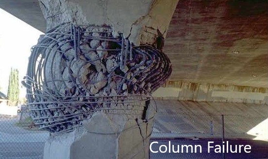
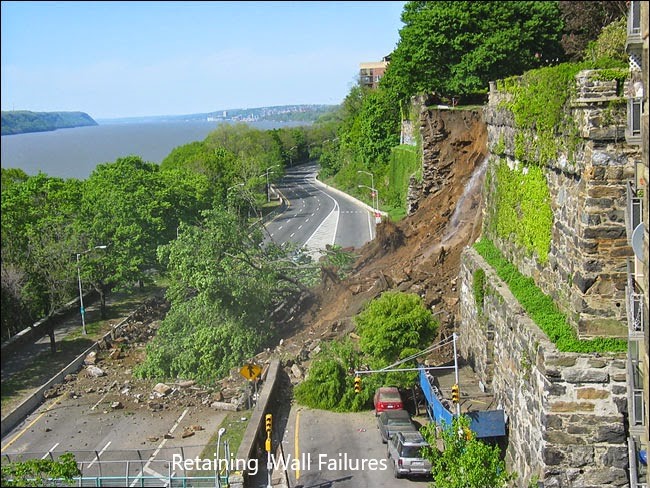
Beam failures could be in flexure, torsion, and shear due to the exceed of the design loads in either failure mode. Depending on the type of load that could exert on the beam and when it reaches the relevant factored load, there is a change of structural failure.
Beam Failures in Flexure
The design of sections is done for the x/d value 0.5 which is less than the balance condition x/d ratio 0.64.
This allows the further distribution of the moment during the loading phase and it encourage ductile failure.
For x/d = 0.5, concrete strains becomes 0.002 whereas it is 0.0035 at the failure. It allows the early warning as the reinforcements yield early and cracks will appear with the increase of the deflection.
Providing excessive reinforcement than the required amount will fail the structure without early workings as the concrete will reach its failure load early.
Failure of the concrete will be sudden and it will be without prior warnings.
However, if the reinforcements are fails, it subjected to yielding and shows deflection with cracking.
When the amount of reinforcement will also be less section will fail. However, it provides warnings by excessive deflections and craking with the application of loads.
If the section is designed following the guidelines given in the code, there will be warnings when it fails.
Warnings will be in the form of cracks and excessive deflection.
Usually, the flexural failures are identified by the cracks.
Depending on the crack pattern it can be concluded whether it is a flexural failure or torsional failure or shear failure.
Figure 01 indicates the cracks that could be observed due to the increase of the bending stress than the design values.
Bending Cracks before Beam Failures
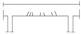
Figure 01 Bending Cracks
Shear Cracks before Beam Failures
When the design shear share stress is exceeded by the applied loads shear cracks can be observed as the initial warning with the increase of the loading.
Immediate attention shall be made in such situations to avoid excessive loads and to investigate the effect of the cracking on the structural elements. Figure 02 shows the cracks appear as shear cracks in a beam.
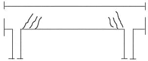
Figure 02 Beam Shear Cracks
Torsional Cracks before Beam Failures
The torsional crack occurs in a section due to the exceed of the torsional moment in a section.
Inadequate torsional reinforcements and incorrect detailing methods could also result in cracking due to the torsional moments.
Figure 03 indicates the torsional cracking of the section.
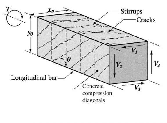
Figure 03 Beam torsional Cracks
Torsional crack patterns of beams are similar to the shear crack pattern. However, torsional cracks continue over the section as shown in Figure 03 than the shear cracks mostly appear only in the sides of a section.
Any of the above types of cracks provide prior warnings as the section are designed according to the guidelines given in the standards.
Necessary actions shall be taken to investigate the causes of cracking and preventive measures and rectification works shall be done to avoid further development of cracks.
Other Types of Beam Failures
In addition to the flexural cracks discussed above, there are other types of cracks that could be appeared in structural elements after the construction work. Mainly they are
- Corrosion Cracks
- Shrinkage Cracks
Corrosion Cracks
Exposure of the reinforcement and concrete to severe environmental conditions could lead to cracking of reinforcements.
Due to the initial cracking of the concrete section, reinforcement could be exposed to the corrosive environment creating a stage that allows to corrosive materials to contact reinforcements.
There are different tests available to check the condition of the concrete and knowing the reinforcement is corroded.
The carbonation test and chlorination test are mainly carried out for this purpose.
Cracks will be in the horizontal direction parallel to the reinforcement as shown in Figure 04. In addition, the formation of the cracks at the bottom of the section could also be due to the inadequate cover to the reinforcements.

Figure 04 Corrosion Cracks
Shrinkage Cracks
There is no regular pattern for shrinkage cracks in a section. They occur in the weak areas and depending on the evaporation of the water from the surface of the concrete. Further, the inadequacy of the reinforcement also causes the cracking of concrete when it drying.
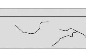 Figure 05 Shrinkage Cracks
Beam failures could be in different modes as discussed above. In summary, methods of failures of beams by different modes of cracking were discussed in the article.
There are a series of articles on beam design including ground beam design that could study to learn more about design aspects.

