Footing rebar details are not that complicated as other types of structural elements. The reinforcement arrangement of the combined footings, spread footings, etc is mainly covered in this article.
We design footing for bending and shear; punching and vertical line shear, and reinforcement are provided accordingly.
Usually, individual footing reinforcement details do not include shear links as we usually try to design them without shear link by controlling the depth of the footing. When it seems we required to provide shear links for the footing, we increase the thickness of the base around the column as indicated in the following figure to enhance the shear capacity.
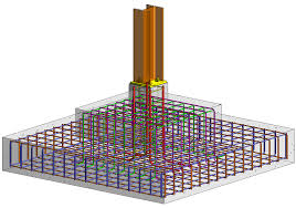
However, combined footing reinforcement details sometimes include the shear links depending on the applied load and the footing geometric properties.
Let’s discuss some of the important footing rebar details and detailing rules. This article mainly based on the BS 8110 Part 01.
Footing Rebar Details and Detailing Methods
Let’s go through them one by one.
- Distribution of Reinforcement
In general, we distribute the reinforcement requirement uniformly. However, when the axial load increases, we need to increase the reinforcement area close to the column where the bending moments and the shear forces are higher.
If lc > (3c/4 + 9d/4), two-third of the required reinforcement should be concentrated within a zone from the centerline of the column to a distance 1.5d from the face of the column.
Otherwise, reinforcement can be uniformly distributed over lc.
here, c – column width, d – effective depth, lc – half the spacing between column centers( if more than once column) or the distance to the edge for the pad(whichever is greater)
- Crack Control Reinforcement
In general, crack control reinforcements are not included for footing rebar details. The unreinforced surface is always in compression when loads are applied. However, when required by the design, we have to provide them.
In the following instances, we could consider providing crack control reinforcements. This information is indicative only, we must check during the design for the requirements.
-
- When the thickness of the footing exceeds 500mm, we may check for cracking. The crack width of the section could be considered and limited as required by the design or specification. Usually, we limit the crack width to 0.3mm for normal structures.
- When the thickness footing increases, reinforcement could be provided to avoid cracking of immature concrete. The article, early thermal cracking could be referred to for more information and method of calculating the reinforcement requirement based on the design crack width.
- Further, the use of higher-grade concrete-like C40 could also lead to the cracking of concrete when the thickness is higher due to the heat of hydration.
- Shear Links
Desing shear links shall be provided as a hook. the typical arrangement of the hook is as follows. The spacing of the hook in either direction shall be as required by the desing.
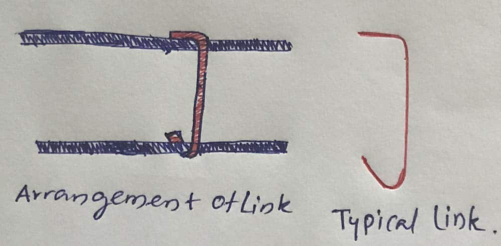
These types of links are provided only when there are top reinforcements and it is required by the design only.
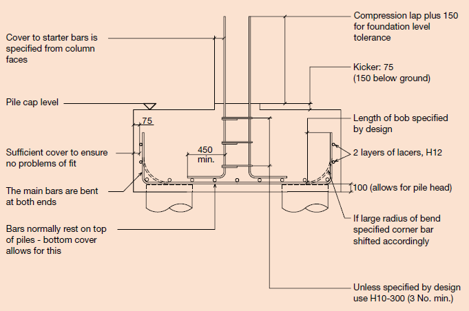
- Typical footing rebar details obtained for the detailing guideline standard method of detailing of structures by IStructE are as follows. This information has developed in line with Eurocode 2.
