Hanger Shear Reinforcement Bars
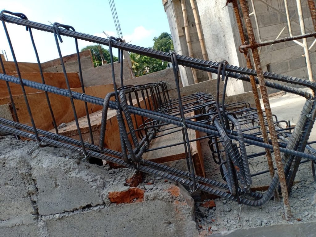
Hanger bars shall be provided in concrete beams that support secondary beams.
Reinforcement shall be provided in the primary beam, and they shall be placed around the joint of the two beams.
Latter figures show the method of detailing of reinforcements.
Design Technique
Generally, we provide primary beams to support the secondary beams.
The reaction of the secondary beams is carried by the primary beam.
We normally design the primary beams for the reaction of the secondary beams, and most of the time many engineers miss the design at the joint.
The joint should be designed to carry the reaction of the secondary beam.
We provide hanger reinforcement at the joint, in the primary in addition to the normal shear reinforcements.
The provision of hanger reinforcement can avoid if the shear force at the edge of the primary beam is less than 3(√f’c)bw2d2 as the inclined cracking is not fully developed at this shear.
Here bw2 is the width of the secondary beam and d2 is the effective depth of the secondary beam.
Method of design and detailing are as per ACI guidelines.
The depth of the primary and secondary beams are h1 and h2 respectively. hb is the vertical distance between the bottom of the primary beam to the bottom of the secondary beam.
ϕAhfyt ≥ (1-hb/h1) Vu2
Where,
ϕ = 0.75
Ah = area of hanger reinforcement adjacent to one face of supporting beam
fyt= yield strength of reinforcement
Vu2= factored shear at the end of supporting beam
Design example
- Factored shear force at end of the supporting beam = 200 kN
- Yield strength = 460 N/mm2
- Primary beam height 600 mm
- Secondary beam height 400 mm
hb = 600 – 400 = 200 mm
Form the above equation,
0.75x460x Ah ≥ (1-200/600) (2x200x1000)
Ah ≥773 mm2
Provide four 12 mm bars
Provided area of reinforcement = 113x2x4 = 904 mm2
Four links are adequate.
There are some other methods as well for designing hanger reinforcements. The book, “Design of Concrete Structures” written by Arthur H. Nilson, David Darwin and Charles W. Dolan also has given a method to calculate the requirement of reinforcements.
They suggested using the ration of the beam height to calculate the required shear force.
Vd = (hsecondary / hprimary ) (Shear force)
For this shear force, we can find the hanger reinforcements. If we use the same concept above, we can write the area of reinforcements as follows.
ϕAhfyt ≥ Vd
Using this we can find the hanger reinforcements.
Click here for more information about shear design.
Beam Shear Design to BS 8110
Beam Shear Design to Eurocode 2


