Lateral loads are applied to structures are needed to be resisted by the lateral resisting systems such as bracings, share walls, frame, etc. All the buildings constructed need to have lateral load resisting systems.
Effect of the lateral load such as wind and seismic loads are becoming critical when the height of the building increases. Different types of structural systems as discussed in article 14 Types of Structural Forms for Tall Buildings could be implemented as required in the high rise buildings.
Lest discuss different types of lateral loads applied in structures. The following types of lateral loads can be observed.
- Wind Loads
- Seismic Loads
- Water
- Earth Loads
- Notional Loads
Wind Loads
The wind is an inevitable lateral load applied to structures. They become critical with the increase in the height of the building. Wind pressure applied to the building and bending moment at the base level will increases when the height of the building is increasing.

Variation of the wind pressure is not uniform over the height of the building. The rate of increase reduces with height. However, there is a different patter of loading for small buildings.
The following figure indicates the typical variation of the wind loads on tall structures.

The variation of the wind pressure shall be calculated based on the relevant standards. Site wind speed, condition of the surrounding area, etc are typically considered to calculate the wind actions.
The following figure indicates the method of applying wind loads on small buildings.

There are different actions of wind loading that can be observed in smaller buildings. Especially in steel buildings, horizontal pressure, vertical upward and downward pressure and suction pressure for the rear wall will be applied.
Since the steel members have less stiffness than the concrete element in a similar nature project, much attention shall be made when designing steel building for winds.
Following standards are used in the world for designing wind loads
- CP3 Chapter V Part 2: 1972 – [3-second gust wind speed]
- BS 6399 Part 2: 1997 – [ Mean hourly wind speed]
- BS EN 1991-1-4: 2005 – [ 10 minutes mean wind speed]
- AS/NZS 1170.2: 2002 – [3-second gust wind speed]
Wind Tunnel Tests
In general, the wind pressure is applied to a structural in two perpendicular directions when they are designed. Further, the wind loads are calculated based on the factors assumed to represent the surrounding environment. However, these assumptions would not represent the actual behavior of the structures.
Cities are developing rapidly. They change suddenly. These affect the wind flowing patter.
Consideration of the actual surrounding environment in wind designs is very important when designing the tallest buildings.
Estimation of the lateral loads on tall buildings correctly is very important. Even if it is estimated correctly to a certain extent, there should be a method to the verify behavior of the structure on actions.

In this background, wind tunnel tests are carried out the check the stresses in the structural element based on the scaled model of the actual structure.
Doing wind tunnel tests is very important in tall buildings to make sure the structure behaves as per the applied load on the computer analysis model.
Seismic Loads as Lateral Loads
There are seven major plates in the earth. We are in one of the plates. Movement of any plate over other causes vibration and as a result it becomes an earthquake.
More the closer the plate boundary the more the magnitude of the earthquake. Depending on the distance to the plate boundaries, seismic zones are established.
The magnitude of the earthquake loads is calculated based on these seismic zones.
There are different codes to calculate the earthquake loads on the structure.
Seismic Loads as per UBC 1997
The following procedure can be used to calculate the base lateral loads exerted on a building.
- Classification of the structure: based on the type of the structure, seismic factors can be obtained from Table 16-N
- Determine the important factor for Table 16-K
- Based on the soil profile type and Sesimci zone factor obtained from Table 16-K, determine the Ca and Cv from Tables 16-Q and 16-R respectively
- Determine the structural period from Equation 30-8
- Calculate the base shear from Equation 30-4
- Check the maximum base shear from Equation 30-5
- Check the minimum base shear from Equation 30-6
- Determine the concentrated force from Equation 30-14
- Find the vertical distribution of the Shear forces from Equation 30-13
Once we calculate the lateral load, we can do the analysis. This is a kind of static analysis method. Calculated shear force can be applied at each floor level. Computer analysis will be more convenient in this type of analysis.
Further, there are other methods like response spectrum analysis and time history analysis methods. They also widely used by structural engineers.
Water Loads as Lateral Load
When we design, water tanks, dams, or any other liquid retaining structures, we use the same method considered in applying the water pressure.
Special attention shall be made when water pressure loads are applied in earthquake situations. If there are earthquakes to be considered, the necessary modification shall be done to the water pressure profile.
When we design the dams, spillways, spillway gates, etc. the variation of the pressure with the height due to the earthquake is considered.
The article Water Pressure Due to Earthquake discuss the method of calculating the variation of the pressure due to a seismic event.
Earth Loads as Lateral Load on Buildings or Other Structures
When there is earth to be retained, necessary calculations shall be done to obtain the correct soil pressure applied to the structures.
Generally, structures are designed for stability initially. The following stability is checked.
- Overturning
- Sliding
- Uplifting
In addition to the above, it is required to check the bearing pressure under the base.
Required safety factors shall be maintained as per the relevant design standard. Generally, the following factors of safties are considered in the design.
- Overturning = 1.5
- Sliding = 1.5
- Uplifting = 1.2
The article Stability Analysis of Structures discusses in detail the methods to be followed when stability calculations are done.
Depending on the restrain conditions, the selection of appropriate lateral earth pressure coefficient is very important. Otherwise will end up with wrong answers.
- Active condition
- At rest condition
- Passive condition
The article Stability Calculation of Retaining Walls discusses the method of calculation of pressure coefficients and provides a worked example for further understanding.
Further, the following equations are sued to calculate the pressure coefficients.
At Rest
Ko = 1-sinφ
Active Pressure
Ka = (1-sinφ) / (1+sinφ)
Passive Pressure
Kp = (1+sinφ) / (1-sinφ)
The article Lateral Earth Pressure Coefficient discussed more on the lateral pressure coefficient calculations and their applications.
Active and passive pressure can be identified quite easily. When the movement of the soil toward the structure, it is an active pressure condition. If the structure moves toward the soil, passive pressure is developed.

At rest condition means, there is no movement of the structure. In general, the lateral pressure applied on the structure is greater than the active pressure condition.
When should we consider at rest condition?
As per the definition, at rest condition represent the no movement of the structure. We can use the at-rest condition in the following occasions.
- We need a rigid structure that has very minor deflections, at rest pressure coefficient could be considered for the calculations. Higher the pressure, the higher the bending moments, and shear forces. Thus, provide a thicker section with a comparative higher area of reinforcements. Then the deflection will be reduced.
- We use at rest condition to design most of the hydraulic structures. They are mostly earth retaining structures. Further, the movement of these structures affects the functionality of mechanical servicers fixed in these structures. For example, gate structures are fixed to the retaining walls and they are mostly taller structures that could taller about 10-20m. Due to the height of the structures, deflection at the top will be significant which may not be acceptable to the mechanical services. Therefore, we design them for a higher pressure for minimizing the lateral deflections.
- Further, there is a tendency to increase the active pressure with time due to various factors. It also considered in these types of structures.
- At rest, the condition is considered for structures that can not be moved due to some restrains. For example, a retaining wall connected to a building and there are not possibilities for considerable deflections. It is advisable to consider the at-rest condition as it could be developed by the soil with the time due to the restrains in the movements.
Notional Loads
All the structures shall be designed for notional loads. It is the minimum load applied to a structure. It covers any construction defect, distributions of the moment, etc. also. However, it is observed that most of the time, it has forgotten to consider notional loads as lateral loads when designing buildings.
For small structures, we apply the notional loads as horizontal load into the building in the analysis.
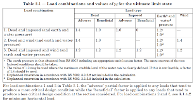
When the wind loads are becoming critical, we compare the factored wind load with the national load and consider the most critical value for the analysis.
Notortiona loads are calculated by considering half the height above the floor and below the floor of floor to floor height. All the dead loads that fall into this area are considered for calculation. 1.5% of the weight is applied as a horizontal force on that particular floor. Similarly, loads shall be calculated for all the floor and ground floor to roof level these loads should be applied after finding the critical load case as mention above.


