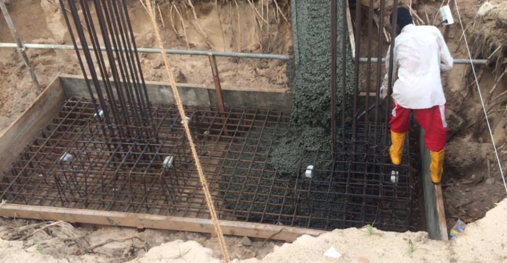
Pile caps are constructed to hold the pile and superstructure together at the ground level or below the ground level while transferring loads of the superstructure to the foundation.
Generally, pile caps are constructed to connect one pile, two piles, three piles, four piles or a group of files. Dimensions of the pile caps are decided based on the loads and connecting arrangement of the superstructure and the pile foundation.
Mainly there are two methods to design pile caps.
- Using the truss analogy
- Using the bending theories
Mostly, up to the four numbers of piles are connected by a pile cap to support the concentrated load from the superstructure, truss theory is used to design the pile caps.
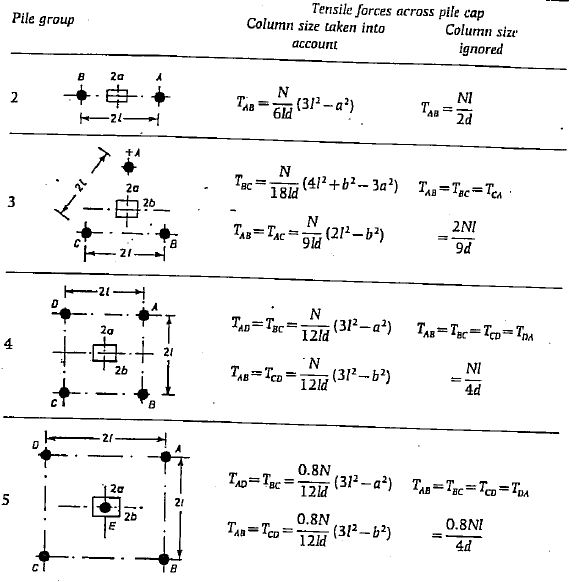
Equations derived considering the strut and tie model are available to calculate the area of reinforcement.
The following figure indicates the typical equations that can be used to calculate the area of tension reinforcements. It was copied from the book Reinforced concrete design to BS 8110.
 When there are more piles, the design could be done using finite element software which makes the analysis easier.
In general, the gap between the piles is kept at 2.5 times the diameter of the piles. It is done to avoid the interaction of one pile on others.
In addition to the calculation of the tension reinforcements, different shear checks like punching and vertical line shear shall be done. When there are more than two piles, the selection of the critical shear perimeter shall be done very carefully. The guideline given in BS 5400 can be used to select the shear perimeter.
Worked Example: Design of Pile Cap
Consider the design of a pile cap supporting two pile and a single column on the pile cap.
Data
- Pile Diameter 600mm
- Design Load 3000 kN
- Cover to the reinforcement 50mm
- Grade of concrete 30
- Characteristic strength of steel as 500 N/mm2
- Size of the column on the pile cap 500x500mm
Calculate the dimensions of the pile cap
consider 150mm offset from the pile and space between piles as 2.5 times pile diameter.
Width = 500 + 150 + 150 = 800mm
Length = 2.5 x 600 + 250 + 250+ 150 + 150 = 2150mm
Consider depth of 1000mm and main bar diameter as 20mm
Effective depth, d = 1000-50-20/2 = 940 mm > 750mm; (2.5×600/2) Ok.
Consider truss theory
Tension Force, T = Nl / 2d
T = 3000 x 0.75 / (2 x 0.94 ) = 1197 kN
As = T / 0.87fy
As = 1197 x 1000 / (0.87 x 500 ) = 2752 mm2
Provide 7 T25 (As provided = 3430 mm2 )
Check for Punching Shear
V = 3000 x 103 / ( 4 x 500 x 940) = 1.596 N/mm2
Vall = 0.8 (fcu)0.5 = 0.8 x (25)0.5 = 4 N/mm2 < 5 N/mm2
Hence, punchig shear is Ok
Check for Vertical Line Shear
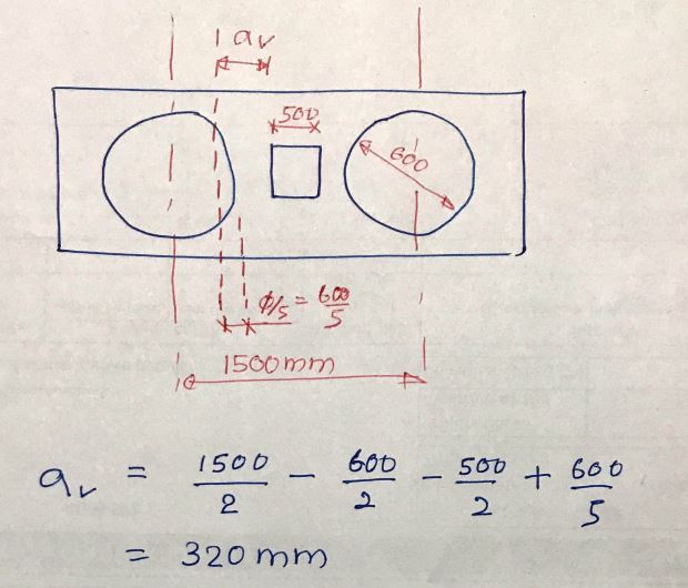
The critical section of the pile shall be considered as 20% of the diameter of the pile inside of the face of the pile. The following figures extracted from the code (BS 8110) provide a clear location to be considered for shear design.
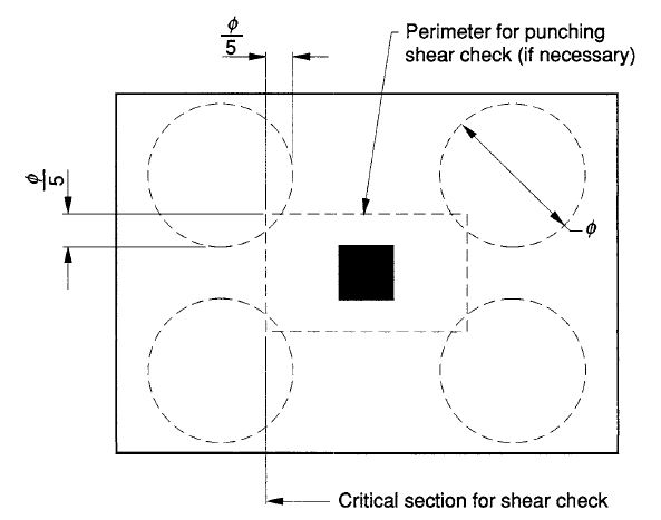 When this section is considered as a critical section and the spacing between the piles is less than or equals to three times the pile diameter, enhancement (2d/av) for Vc can be considered. Here, av is the distance from the face of the column to the critical section.
In this example, we considered only two piles as shown in the following image.
 Vc and be calculated from Table 3.8 of BS 8110 based on the 100As/bd value.
100As / bd = 100 x 3430 / ( 1000 x 940 ) = 0.365
Vc = 0.446 N/mm2
Enhanced shear capacity ; (2d/av)Vc
(2d/av)Vc = ( 2 x 940 / 320 ) x 0.446 = 2.62 N/mm2
Desing shear stress = 1500 x 103 / (1000 x 940) = 1.596 N/mm2
Hence Ok.
Calculate Area of Distribution Steel
Consider the minimum reinforcement requirement.
100As / Ac = 0.13
As = 0.13 x 1000 x 1000 / 100 = 1300 mm2 / m
Provide T16@150 mm c/c (As Provided = 1340 mm2
Area of Horizontal Binders
Provide 25% of the design reinforcements
As binder = 0.25 x 2752 = 688 mm2
Provide T12@150 (As provided = 754 mm2 )
Similarly, other types of pile caps can also be designed following the same procedure. However, when the number of piles is increasing in a pile cap, the manual calculation becomes more complicated. Computer packages could be used for ease of design while verifying the design outcome with simple calculations.
Design of single pile cap is not the same. Connection of the column and pile is made by pile cap. The article Design of Pile Cap| Design of Single Pile Cap discussed the more information related to the pile cap design.