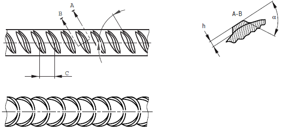
Rebar rib is the component that established the bond between the concrete and the reinforcement. Therefore, it is very important to study the surface geometry of the reinforcement steel.
When the reinforcement place within the concrete, it acts as a composite material. The contribution of the reinforcement is made with there is a proper bond between the concrete and reinforcements.
The stress with the concrete and steel is mainly developed by the rebar ribs. The surface geometry of the rebar is the main factor that contributes to bond stress development.
The article design anchorage bond stress could be referred for more information on bond stress calculation according to the BS 8110.
We are concentrating on the rebar rib geometry specified in the BS 4449: 2005.
Surface geometry reinforcement bars are discussed with reference to the following.
- Dimensions of Ribs
- Number of Ribs
- Configuration of transverse and longitudinal ribs.
The following information or parameters/dimensions are considered to specify the rib geometry.
- Rib Height
- Rib Spacing
- Rib Inclination
The following figure indicates the typical arrangement of rebar ribs.

BS 4449: 2005 has specified the allowable range for the rib heights, rib spacing, and rib inclination.
| Rib Height, h | Rib Spacing, c | Rib Inclination, β |
| 0.03d to 0.15d | 0.4d to 1.2d | 350 to 750 |
Where, d – is nominal bar diameter.
The characteristic relative rib area shall be as shown in the following table. (p=0.95).
The method for the calculation of relative rib area shall be as per the BS EN ISO 15630-1:2002.
| Nominal Bar size, d / mm | Relative Rib Area |
| d ≤ 6 | 0.035 |
| 6 < d ≤ 12 | 0.040 |
| D > 12 | 0.056 |
Transverse Ribs
The following parameters are considered for rebar rib geometry as specified in the BS 4449.
- Transverse ribs shall approximate to a crescent shape, and ti shall merge smoothly to the bar.
- Projection of the transverse ribs shall extend over at least 75% of the circumference of the bar. Nominal diameter shall be considered for this calculation.
- Transverse rib flank inclination α shall be greater than or quail to 450, and the transition from the rib to the core shall be reduced.
This criterion is the same as the code.
Longitudinal Ribs
The height of the longitudinal ribs shall not exceed 0.1d when they are added to the reinforcement bars.


