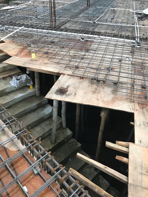
Design for shear is one vital thing to look at when designing structural elements. Cracks will appear and give sufficient warnings due to the lack of the shear reinforcements. Shear design can be done by considering the shear enhancement. Shear force is considered at a distance equal to the effective depth from the face of the support.
Shear design can be done with the equations or with the data given in the table in the BS 8110 Part 1. Designing with the table is a comparatively easy method compared to the other method. Table 3.8 can be seen below. We can calculate Vc value from the following table if we know the effective depth, the effective width of the section and the area of the tension steel.
Once we calculated the value of Vc, we can find the spacing of the shear links from the following table.
Design Data
Share force = 250 kN
Height of the section = 500 mm
With of the section = 225 mm
Concrete Grade = 25 N/mm2
Steel Yield Strength = 460 N/mm2
Shear Link diameter = 10 mm
Area of tension steel = 1470 mm2
Effective depth = 450mm
Design shear stress = V / bd
= 250×1000 / 225×450
= 2.469 N/mm2
100As/bd = 100×1470 / (225×450)
= 1.452
From table 3.8
Vc = 0.715
Asv ≥ bvSv(V-Vc) / 0.95fyv
2×78 ≥ 225xSv(2.469-0.715) / 0.95×460
Sv ≤ 159 mm
Provide T10 bars at a spacing of 150 mm.
We do not need to continue the same spacing throughout the span. The spacing of the links can be adjusted to minimize the cost of the construction. In general, a higher shear force can be seen at the supports and it reduces towards the mid of the span. Hence, we can provide links at a higher spacing in the middle of the span.
Assume, we are planning to provide shear links at a spacing of 250 mm in the middle part of the span. Using the above calculation we can back-calculate the shear capacity for shear links at a spacing of 250 mm. Once we know the share force we can find the distance that we need to prove the shear links at a spacing of 150 mm.


