Dams are constructed to retain the water or to avoid water movements. Different types of dam constructed worldwide are discussed in this article.
Depending on the type of materials used, the nature of the structure, structural from, etc. dams can be categorized. There are over 10 major categories of dames that can be found in the world.
Arch dam, buttress dam, rockfill dam, earth dam, etc. are discussed in this article.
The more conventional and simplest types of dam are the earth dam where we can observe mostly.
What is a dam
This is the big question to be as throughout this article…
A dame is a structure built to retain the water. It could be a combination of several structures or a single structure.
A large dame that is built for getting water for drinking and irrigation mainly will have dame body spillway, outlet structures, embankment structures, etc.
In addition, there are options for power generations. Thus, depending on the purpose of the structure, the addition of the structures to the dams is made.
Mainly, the following structures are constructed connecting/connected with the dams.
- Spillway:
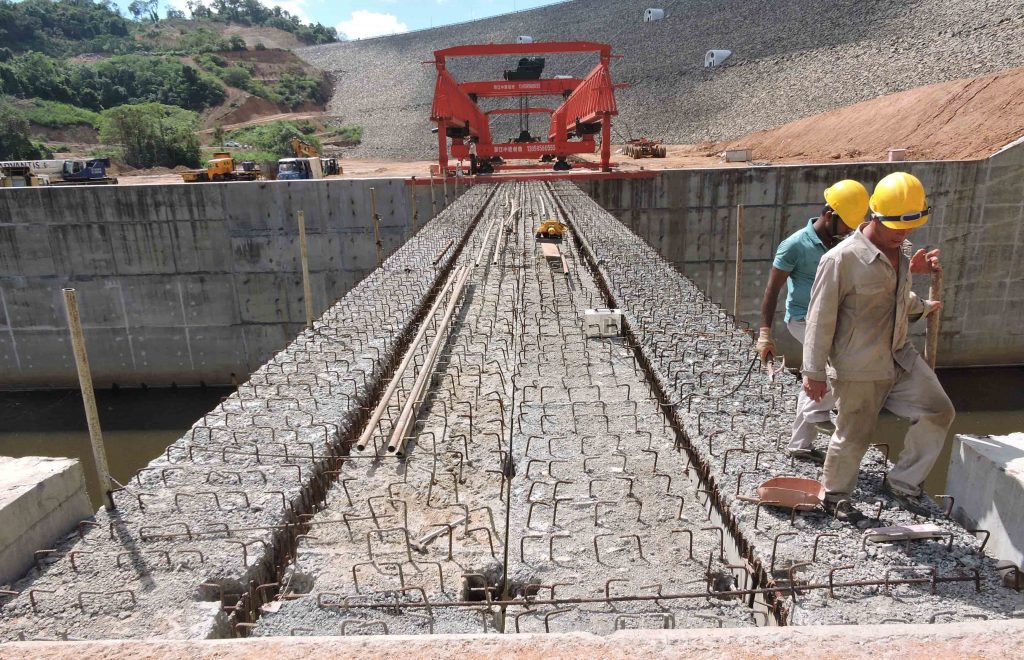
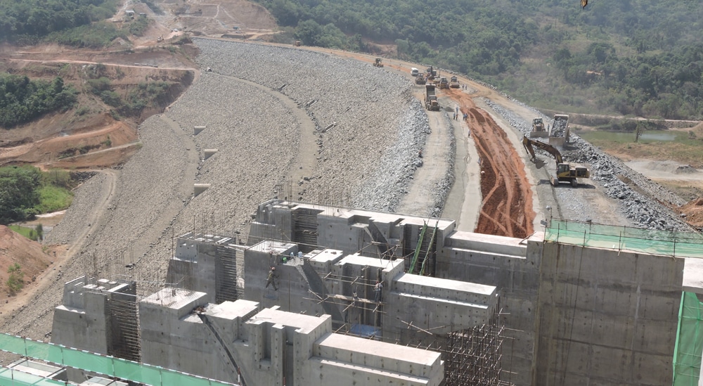
It is the key structure construct connecting to the dam body. Whether the dam is concrete, rock fill, earth, etc. spillway is constructed to control the additional water collected in the reservoir and to maintain the reservoir at the optimum operating level. The elements such as ogee, weir, gates, control systems, gatehouses, chute, and stilling basin are the key structures included in the spillway. In addition, there could be bridges mostly post-tensioned, over the spillways.
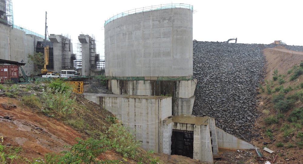
- Guide Walls:
Usually, there are guide walls beside the spillways. One could be work as the abutment to the embankment as indicated in the above figure. The other one (on the right) constructs to act as the abutment to the dam. Guide walls are fairly large structures as mostly in the hydraulic structures.
Most of the hydraulic structures are falls in between the gravity and the retaining wall structures. They are provided reinforcement to carry the forces.
In addition, due to the limitation of the deflection also, fairly higher thicknesses are used in the design and construction. For example, when the dam body is connected with the guide wall, if it moves due to the lateral load, the dam could fail due to the movement in the dam body in the direction of the wall. The lateral deflection will be higher for these structures if they do not have adequate lateral stiffness as the retaining height are very high.
Further, it is required to limit the deflection of the spillway side walls to operate the gate structures properly. The excessive lateral movement could cause the mechanical system to fail.
- Diversion Tunnel and plugs:
Construction of diversion tunnel or structures and concrete plugs are quite common in any types of dam. Dams are constructed across the rivers or water paths to stagnate the water. In the construction period of the dam, existing water needs to be diverted in a different direction or it should be sent to the downstream without obstructing the construction. When there is a solid rock in the area where the dam is constructed, a tunnel is constructed under the dam body or in a closer area to divert the water.
Diversion tunnel shall design and constructed considering the maximum discharge that could occur in the river. The hydrological studies done especially on this shall be the base for selecting the size of the tunnel. In the design of the dam and the spillway, these data are considered. Hence, these data will be available and the same can be used to design the diversion tunnel.
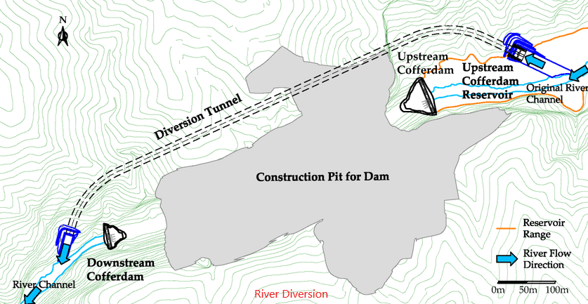
After the construction of the dame, it is required to close the diversion of the water. The mechanism that uses them to stop the water movement or seal the tunnel is called a concrete plug. A concrete plug is a mass concrete or reinforced concrete fill that constructed to seal the tunnel. After concreting the plug, injection of the grout is done to make sure there are no cavities in the concrete especially at the top of the plug.
- Bottom outlets: The name itself provides an idea about the structure. Bottom outlets are constructed in reservoirs at the lowest level of the structure. It consists of a gate structure that enables the release of the water.
Release ecological discharges which required to maintain the stability of the environment and for cater the requirements of the downstream uses, use supply water for downstream irrigation systems existed before the construction of the dam, release the extra water from the reservoir, use to lower the water level of the reservoir for maintenance work, etc. are some the most important uses
- Transfer channel and tunnel: The transfer channel is constructed to divert the water in a reservoir to some area or to another reservoir. When there is a small dam that is able to collect water, transfer channels are used to send water to the main reservoir.
A transfer channel could be an open channel or tunnel. At the starting form the reservoir, it is mostly a tunnel. However, beyond a certain distance, it could be constructed as an open channel based on the topography of the area. Further, the construction of a tunnel is a costly option.
- Irrigation water supply: On of the most important purpose of a dam is to use the collected water in the reservoir for irrigation. Irrigation outputs are constructed as tunnel structures at the beginning of the water supply. Same as the transfer channels, these structures are also constructed in a similar manner.
- Intake for power generation and Power station: Most of the major dams are constructed for generating hydropower. It is one of the energy sources that does not make any harm to nature.
Intake structures are constructed connected to the dam or in some other place in the reservoir that has the adequate head or at the location where it creates the maximum head. Water head is one of the most important energies that converted to electricity. Base on the design, especially when the high head is used for power generation, power stations are constructed far away from the intake.
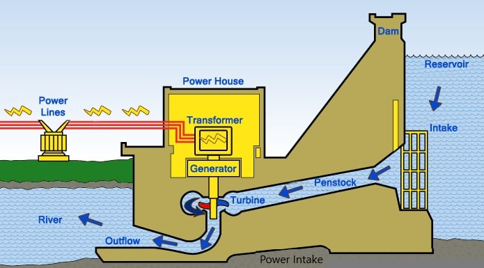
When the discharge is based turbines are used, where it is not possible to have a higher head, power intake and power station are very close to the dam. Power station could be constructed as part of the dame structure when the dame is a concrete structure or it could be constructed jointly.
- Grout curtain: It is the main obstruction to the movement of the water under the dam body. Even though most types of dam are constructed in rock foundations, there could be seepage paths, cavities, etc. where it enables the movement of the water.
Rock is not impermeable. It has to be grouted to fill the cavities, cracks, weathered zones, etc. extend and the number of grout holes or the pattern of the grout holes shall be as per the condition of the rock.
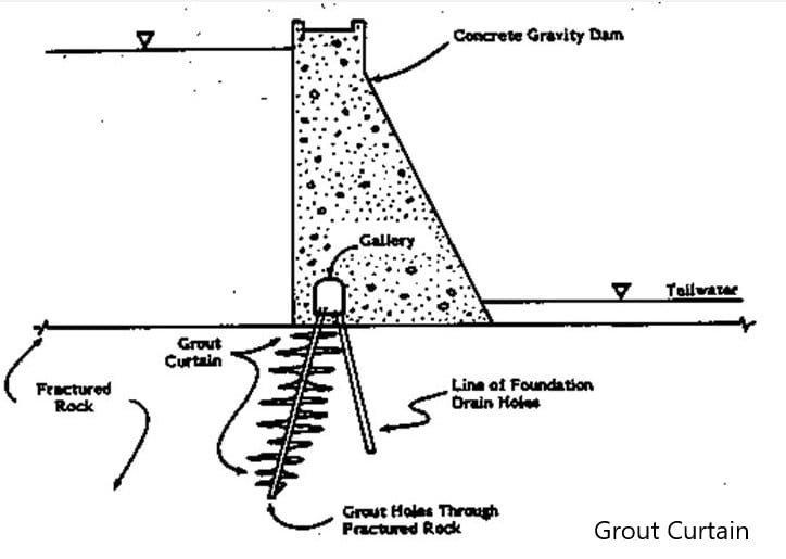
In some of the dams, an inspection gallery or the grouting gallery is constructed to do the necessary grouting even after the construction base on the seepages in the downstream.
In addition, the construction of a grout curtain reduces upthrust or the uplift pressure on the dam. It reduces the dam stability issues significantly.
- Saddle dam: If briefly outlined about saddle dams, it is one of the types of dam which could not be that big as the main dam that constructed to avoid the movement of the water when the reservoir getting filled. The dam creates a reservoir where it spread over a larger area.
The following figure taken from the internet indicates a saddle dam.
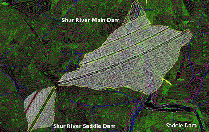
There could be places that need blocking the movement of the water when the water level rises. Those small dams are called the saddle dams. However, in some situations, a saddle dam may also be a large dam as the reservoir getting larger.
- Cofferdam
A cofferdam is a part of the work related to the most of the types of dam construction. Cofferdam construction is not limited to the dam construction and it is quite common in construction below the water level.
As discussed under the diversion tunnel, the river need to divert for enabling the construction to proceed smoothly in both the dry and rainy seasons.
The temporary dam or the structure build across the river is called the cofferdam.
The following figure indicates a type of cofferdam constructed in the construction site.
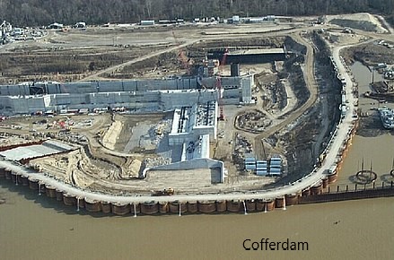
Though the cofferdam is a temporary dam, it shall be designed with much care to avoid failures. Overtopping or failure of cofferdam will affect severely to the construction work of the main dam.
Therefore, probable risk shall be minimized considering the adequate return period for flooding.
The Wikipedia article on cofferdam also provides detailed information on this subject.
Lets now discuss the different types of dam in the world.
Earth Dams
Earth dam is also called an embankment dam. Since the earth is used to construct these types of dam, they are also called earthfall dams.
Earth dams are constructed using impervious materials such as clays. Depending on the design, the placement of the impervious layer could be at the core and other material could be placed beside the core.
The following figure indicates the typical arrangement of an earth dam.
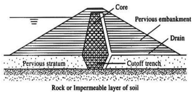
The above figure indicates the basic arrangement of the earth dam. There could be more additions in a complete dam that enhance the function and safety of it.
The dam core could be continued up to the impervious layer to avoid them and minimize the seepages. Constructing a core as indicated above will minimize the seepage. However, we can not completely avoid the seepages.
Therefore, a drain will be constructed downstream side of the dam. The drain could run along with the core and away from the dam towards the downstream as indicated above figure.
The selection of the material for the drain shall be done carefully. In the latter part of the article under dams, we discuss the material selection for each layer.
As per some of the findings, 33% of the dame failures are due to excessive seepages. Therefore, selection of material and dam design is very vital.
Mainly there are two types of earth dams.
- Homogeneous dams: use the same material to construct the dam body as indicated in the following figure. However, other components such as drains, dam slope protection will be done with suitable materials.
- Zone type: The main difference of the zone type dams is the addition of a central core. Construction of the zone type dam is more suitable for larger dams.
In addition to the above method, dams can be categorized as indicated in the following figure.
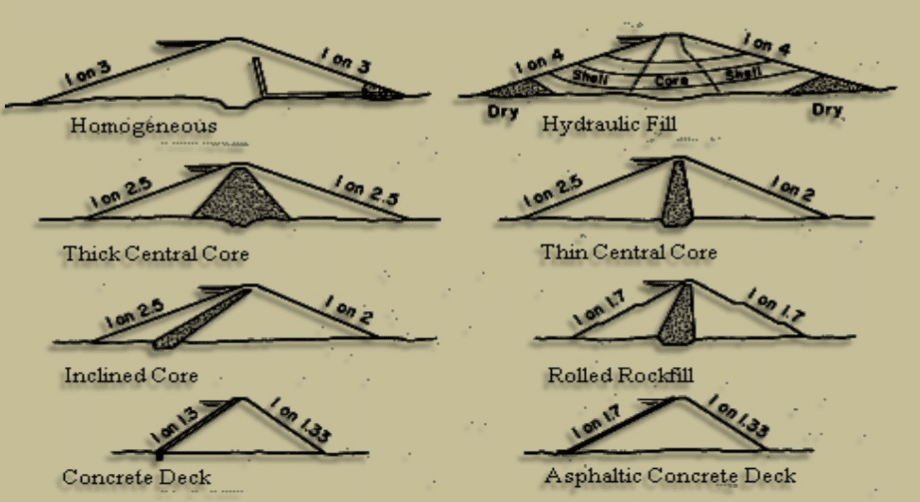
The selection of the slope of the earth fill is the vital factor in the sense of stability. The available slope in already constructed dams could be used in the initial design.
The selected slope shall be checked for its stability. It could be done with the manual calculation or suitable software could be used for the calculations.
The use of suitable software is the best option to analyze these types of dam. We can get the critical factor of safety based on different failure planes.
Material Selection
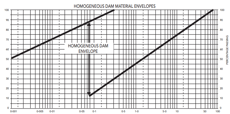
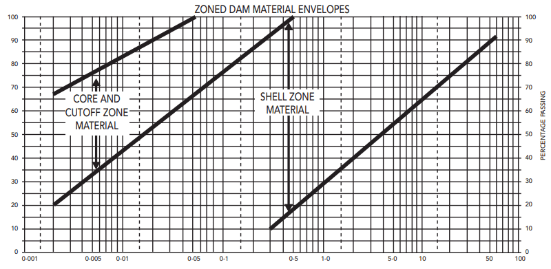
The selection of suitable material for the earth dam is a very vital factor. The following figures indicated the selection of materials for different occasions
- Homogeneous dam material envelopes
- Zoned dam material envelopes
- Filter and drain material envelops
A similar chart should be developed for the dam based on the design. The figures indicated below are a selection of materials based on the gradation of the materials. Further, similar nature charts will be developed for these types of dam.
In addition to this method, there are other tests such as shrinkage limit, plastic limit, liquid limit, etc could be done to make sure the material is suitable.

Earth Dam Failures
- Hydraulic Failures: Mainly there are five methods that these types of dam could fail due to the hydraulic actions.
- By overtopping
- Erosion of upstream slope
- Cracking due to forest action
- Erosion of downstream slope
- Erosion of downstream toe
- Seepage Failures: According to some of the findings, more than 33% of dams fail in seepage. Therefore it is very important to pay attention to the selection of the material during the design and providing adequate drainage. Further, drain material selection shall be done correctly in order to function as required. Causes: piping through the body of the dam, piping through the foundation,
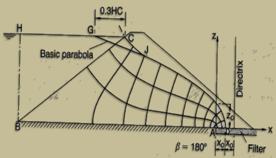
The above figure indicates the seepage paths that could be observed in a dam that does not have a core in the middle. A similar kind of seepage movement can be expected in the dams. Therefore, proper drainage arrangements shall be provided to avoid dam failures.
Some of the seepage failure methods can be highlighted as follows.
-
- Piping through the body of the dam
- Piping through the foundation
- Structural Failures: Failures that cause in the dam body fall under this category.
- The upstream and downstream slope
- Sudden draw-down
- Faulty construction
- Improper maintenance
- Eeartquake Failures: Earth dams could fail in earthquakes due to the increase of the water pressure due to the movement of the water or due to the failure of the dam body.
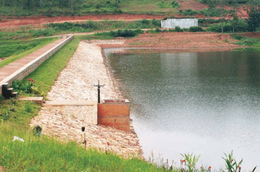
The following figure indicates a completed dam.
Rockfill Dam
Dams that constructed using rock and impervious materials. Rockfill dams are more popular especially when the required materials are readily available.
Rockfill dams are zone type dams that include different zones such as core, shell, filter, drains, etc.
Let’s see what are the main component of these types of dam.

Every zone has been numbered for ease of reference. They are as follows.
- Core
- Filter
- Transition
- Downstream fill
- Riprap
- Rockfill
- Coarse FIll
- Cohesive fill
Out of above, let’s discuss some of the important zones in a rockfill dam
Core
Dam core is the hart of the dam body that resists the movement of the water. It is stabilized itself and rockfill placed on both sides of the core.
Clay is used as the core material and its selection is made based on the particle size distribution and based on the tests such as liquid limit, plastic limit, shrinkage limit, etc. Most types of dam constructed worldwide consider maintaining the consistency and quality of cay used for construction.
In addition, the permeability criteria also check the make sure it is within the acceptable limit.
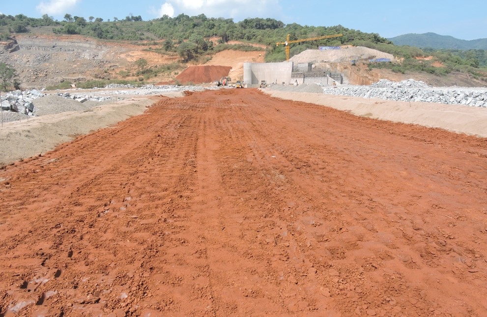
As indicated in the above figure, the dam core is filled and compacted with suitable materials. Filing is done in layer and each layer is placed between two abutments and compacted.
No stage construction or the vertical joints are made in the core.
As we know, there is an optimum moisture content to achieve the maximum compaction. Thus, controlled spraying water is done during the compaction.
In addition, special attention shall be made when selecting the slope of the core. Information on previously constructed projects and stability requirements can consider selecting the most suitable slope.
FUther, stockpiles are more common on these types of dam to proceed with the construction without a delay.
Filter
The filter is the material that is placed next to the core. Even though we expected core to be impervious, it has a permeability.
Water seeping through the core towards the downstream needs to get filter carefully without washing or losing the core materials. Thus, filters are designed to smooth the transition of seepage water.
There are design charts based on the particle size distribution, specifying the range of the particle sizes that should be selected for the filter. A similar type of chart indicated under earth dam design will be available for reference.
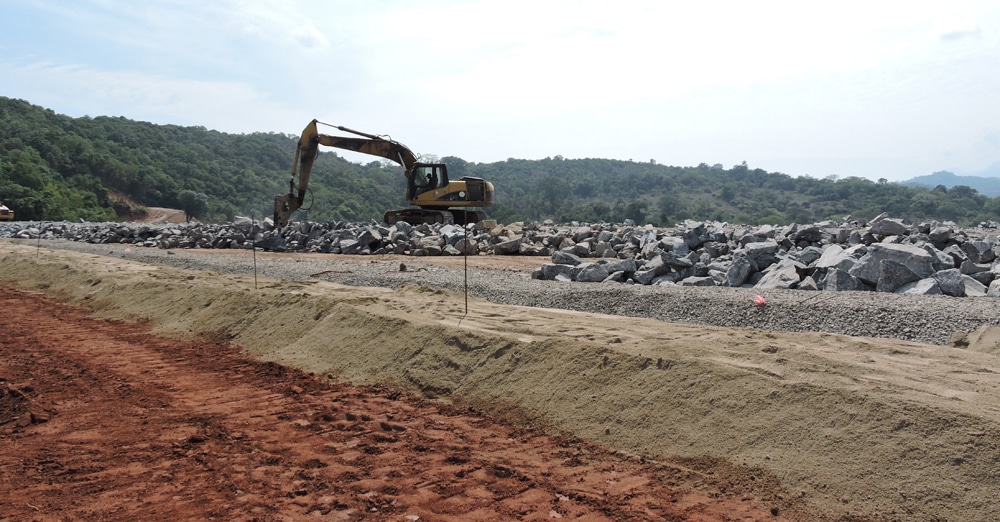
The fine material indicated next to the core material is the filter material. The filter is also placed together with the dam core material. Initially, the transition and filter materials are placed. Then core material is placed in between the filter materials on either side.
There are two filters on either side of the dam as indicated in the typical zones in these types of dam. The upstream filter also provides protection to the core and maintains the smooth movement of the water.
Further, when there are sudden drawdowns, the upstream filter acts the same as the downstream filter and protects the core from getting washed.
In addition, having a filter in the upstream in such situations, it controls the rate of lowering the water level in the core. If the water level is lowered suddenly in the core, it adversely affects the core stability.
Transition
Transition is the zone where the connection of the shell is maintained. It is used to change the particle sizes gradually to the larger size.
The filter is fine material and rockfill is having large size rock. Transition material is placed in between to make it a smooth change of materials.
The particle size distribution of the transition materials shall also be controlled during the construction as per the project specification. Similar to the filter material, there are charts that shall be used in construction when selecting the size of the transition materials.
In the above, figure, the metal fill next to the filter material is the transition.
Riprap
Riprap is constructed to protect the dam shell due to the movement of the water.
When the waves contact the dam body, it could lead to slop failures. The energy in the waves shall be dissipated properly without making any harm to the dam.
Further, the construction of riprap is more important for earthfill dama. However, even for rockfill dams, the construction of riprap is a good option when dam safety is considered.
In addition, there is no much difficulty in forming the riprap for these types of dam as the shall materials are available.
Rockfill
The major quantity of the material used in these types of dam is the rockfill.
As the name implies, the rockfill dam is constructed using the rock. This is a stage construction where each later of transition, filter and core is placed after placing the rockfill.
Rockfill shall be compacted adequately as specified in the specification and necessary testing shall be done to make sure the compaction is adequate.
In dam construction, when the height of the increases, berms are constructed to increase the stability of the slope.
Stability analysis of the rockfill dams shall be done for both normal and exceptional events such as earthquakes. Since it involves huge costs for the construction of a dame, it should be stable in any probable event.
Most probable earthquake, probable maximum flood, etc. are considered during the design.
The slope of the rockfill is the key factor affecting the stability of the dam. The selection of the slope of the dame shall be made based on the profiles of the available dams as an initial profile. Once selected, it shall be checked for its stability. Mainly, the slope stability is checked in dams of this nature. The minimum factor of safety against usually loads and unusual loads is checked.
Factor Safety Against Overturning
The following table indicates the factor of safties could be considered in the stability analysis.
| Design Situation | Minimum Factor of Safety |
| Full Service Level | 1.5 |
| Minimum Operation Level | 1.5 |
| Empty Reservoir | 1.5 |
| Rapid Draw Down | 1.3 |
| Operating Basis Earthquake | 1.3 |
| Maximum Credible Earthquake | 1.1 |
The above values could be varied from standard to standard. However, there could not be a considerable difference for these types of dam.
Stability analysis is done using computer-based software to get more accurate results. However, in the analysis, the correct idealization of the actual dame shall be done to get the correct results. Further, material behavior shall also be considered more precisely in the analysis.
We can get the critical factor of safety from the software for the most critical slope. Softwares like Slope/w could be used to check the stability of the dam.
Factor Safety Against Sliding
The dam should be check for the sliding against the lateral loads applied to it.
The minimum factor of safety shall be maintained against usual and unusual (earthquake) events.
The following limitations could be adopted as stipulated in EM 1110-2200.
| Design Situation | Global Factor of Safety |
| Usual Situation: Normal operation loads | 2.0 |
| Transient Situations: Construction stages | 1.5 |
| Exceptional Situation: Extreme water levels, earthquakes, etc. | 1.3 |
Seepage Analysis
The dam shall be checked for the seepage movement. It provides a clear understanding of the movement of the water through the dam body and dame foundation.
The software like SEEP/W could be used in the analysis.
The outcome of the analysis could be used for the design of the dam. Further, we can find and study the development of the water pressure on the dam and structures connected with the dam.
For example, concrete spillways are constructed together with the rockfill dams. Spillways are also constructed as gravity structures. However, due to the water height, there will be significant uplift pressure on it. Further, it could coarse stability issues. On some occasions, rock anchors are provided to maintain the stability of the dam.
Further, the clay core is one of the most components of these types of dam. Failure of the core material will lead to failure of the dam. Therefore, carrying out a study on seepage, and interpreting the outcome correctly is much important.
Dam Instrumentation for Dam Safety
During the construction and after the construction, it is required to monitor the performance for dam safety. Performance can be monitored and compare with the design to make sure it behaves according to the design.
It is a well-known fact that the use of dam instrumentations have provided the proper reflection of the construction to the engineer to compare it with design in these types of dam.
During the construction of the dam, we can check the dam settlement from the instrument embedded in the dam body. If there are unexpected behavior is observed, necessary modifications/actions can be taken during the construction.
The following dame instruction is done in rockfill dams. In other types of dam also, some of these instruments are fixed to maintain the dam safety.
- Dam Monitoring Survey
Surveying methods are implemented to monitor the vertical and lateral displacement of the structures.
- Vertical Deformation Pipes
It provides internal vertical and horizontal displacements. The horizontal displacements are measured manually by an inclinometer and the vertical displacements are measured and recorded manually by a magnetic settlement probe.
This is very useful in finding both the absolute settlement and vertical compression (strain) in embankments and foundations.
- Settlement Cells
It provides vertical displacement or the settlement. When it is installed in the foundation, settlement of the foundation can be obtained.
Settlement cells are mainly used in the construction stage and dam impounding stage for monitoring the vertical displacements.
They do not last more than 5-10 years if they are not maintained properly.
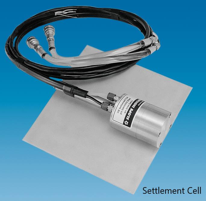
Further, monitoring the settlement of the dam is a must for these types of dam construction.
- Accelerometers
Accelerometers are also called as three-dimensional motion sensors.
They are used to monitor the dynamic reaction of the dams by earthquakes.
- Standpipe Piezometers
They are also called as open tube standpipes or Casagrande piezometers.
Installed to monitor the piezometric water level in the foundation adjacent to the dam area.
Further, this provides information on the effectiveness on sealing by clay cores and grouting and possible leakages.
- VW Water Pressure Transducers
Cells are placed inside the clay core of a rockfill dam. It monitors the pour water pressure development in the clay core during the construction and after the construction.
During the construction, they provide data related time for the consolidation of the core and response of the pore pressure with reference to the design considerations.
After the construction, they provide the information on the effectiveness sealing by the clay core material in the sense of pore pressure gradient.
Further, VW water pressure transducers can be used in combination with open tube piezometer standpipe to find the effectiveness of sealing of grouting connection to the clay core and possible leakages.
In addition, VW water pressure transducers are used to check the condition of the downstream filter. We can check the possible water heads indicating blocking the free drain.
In addition to the above, seepage discharge measurements and reservoir and tail water level measurements are also taken.
Arch Dam
According to Wikipedia, arch dam is defined as a concrete dam that is curved upstream in plan. The arch dam is designed so that the force of the water against it, known as hydrostatic pressure, presses against the arch, causing the arch to straighten slightly and strengthening the structure as it pushes into its foundation or abutments.
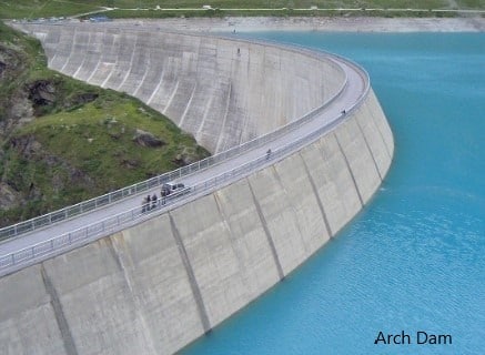
There are different categorizations such as based on thickness, height, geometry, etc. of arch dams.
Let’s how to categorize different types of dam in this category.
- Constant Radius Arch Dams
A constant radius is maintained in the arch dam at outer and inner surfaces. Further, it is constant at the centerline of the dam also.
This type of dam is also called the single curved arch dam.
- Variable Radius Arch Dams
Both the internal and outer radii are varying with the height of the dam. It starts with a small radius at the base level and it increases with the height.
The radius is varied in this type of dams with the variation of dam radius.
Generally, the variable radius dams are economical than the constant radios dams. In constant radius dames, the thickness will remain the same through the height. However, in variable radius arch dams, concrete thickness reduces with the height.
Further, Variable radius arch dams are more suitable V-shaped valleys.
- Double Curved Arch Dams
Concrete dams having the curvature in vertically and horizontally are falling under this category.
Due to the curved shape in either direction, it optimizes the design and maximizes the load transfer mechanism. Further, double curvature dams need less thickness comparatively due to their behavior.
The requirement of a strong foundation and high cost of construction is the key disadvantages of this type of dam.
Since, the dam curved in both the direction, preparation of formwork is more difficult than other types of dam.
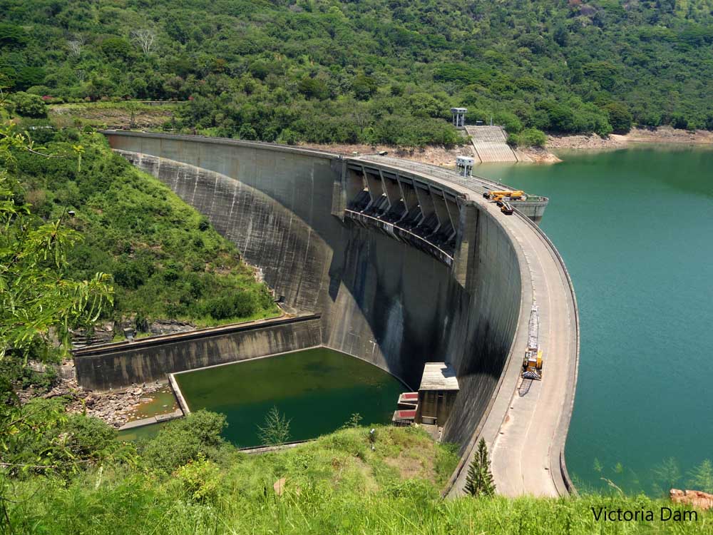
The above figure indicates the Victoria Dam (Sri Lanka) having double curvature.
There are other categorizations of arch dams based on the thickness and the height of the dam. These types of dam categorizations provide the better idea about the scale of the project.
Classification based on Base Thickness to Height Ratio
| Dam Type | Base to Height Ratio |
| Thin arch | < 0.2 |
| Medium-thick arch | 0.2 to 0.4 |
| Thick arch | 0.4 to 0.65 |
| Curved Gravity | > 0.65 |
In addition to the above, arch dams are categorized based on their heights.
Classification based on Dam Height
| Dam Type | Dam Height |
| Low Dams | Up to 30m |
| Medium height dams | Between 30 – 91 m |
| High dams | Over 91 m |
Advantages of Arch Dams
- Arch dams are more suitable for valley have lesser width comper to its height. Constructing cantilever gravity dams such as rockfill dams may not be economical as higher base width is required.
- Since comparatively lesser thickness is used for dam body, the cost could be lesser
- Further, the use of concrete reduces the elements. Since the arch dames are supported by rock mass, there will not be movements other than that causes due to creep, shrinkage, and elastic shortening.
- There less difficulty in finding the construction material as the costly construction is done with concrete. In rockfill dams or earth dams, there are difficulties in finding core materials in big quantities having the same consistency that satisfy the technical requirements.
Disadvantages of Arch Dams
- Construction is difficult due to its geometry.
- Need more technology into the construction to make it easy.
- Installation of formwork is comparatively difficult due to the curvature
- Less speed construction
- Very high attention is required on factors affecting durability of concrete.
- Long term and short term effects due to creep, shrinkage, and elastic shortening could cause issues.
- Cracks in the concrete could become a severe issue
- Conditions of rock at foundation and abutments shall be strong enough to bear the applied loads.
Buttress Dam
Buttress dam is a kind of a gravity dam that provides stability by its own weight. It is supported by buttresses or other support constructed in a regular interval. Further, these types of dam are not common in the world.
Let look at a buttress dam before the further discussion you to get an idea about what we are going to discuss next.
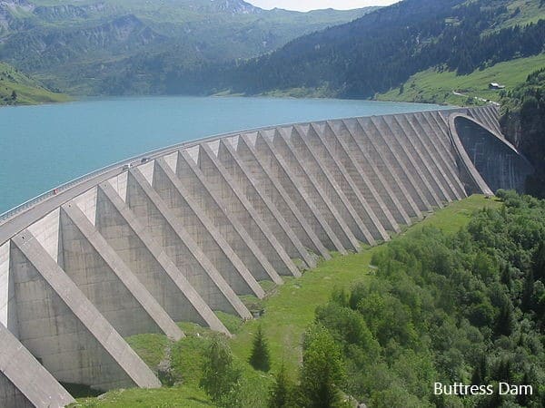
As it appears in the above figure the will be supported in similar nature or different patterns to support the dam shell.
The following points can be highlighted in connection with this type of dam.
- Buttress dam is a gravity dam which provides the stability for usual and unusual loads.
- The water pressure applied to the dam shell transfer to the foundation with the support of the buttresses.
- Due to the supports provided by buttresses to the dam body, stress in the dam body reduces.
- The concrete strength may not be effectively utilized due to the support provided.
- With the increase in the base area, uplift pressure will be increasing. Hence, the weight of the structure needs to increase to maintain sufficient factors of safety. (We discussed a factor of safety against overturning and sliding in rockfill dam above)
- However, due to the buttress provided, it reduces the total volume of concrete.
- The front thin shell is vulnerable to durability issues. Therefore, attention shall be made on durability requirements.
- Cost for formwork is higher
There are different classification of buttress dams. The following is considered in this article. Further, there are other subcategories under each category.
- Rigid Buttress Dam
- Deck Slab Buttress Dam
- Bulk Head Buttress Dam
Rigid Buttress Dam
This is more simple type of structure. The sloping membrane or the deck is constructed together with the buttresses. Since they are constructed in large volumes, technical aspects such as the rise of temperature in the concrete, settlement of the structure, etc shall be attended with much care.
Mainly there are two types of rigid buttress dams.
- Multi arch dam
- Multiple dome buttress dam
Deck Slab Buttress Dam
It is constructed as flat slab/deck support by series of buttresses. Further, this is also a reinforced concrete structure.
In addition, the spacing of the buttresses is depended on the height of the dam. Since the spacing of the buttresses is related to the stability of the cost of the construction, they shall be selected with much care.
As a rule of thumb, the spacing of the buttresses could be varied between 5-15m.
Mainly there are three types of deck slabs.
- Fixed Deck Slab Buttress Dam
- Simple Deck Slab Buttress Dam
- Cantilever Deck Buttress Dam
Bulk Head Buttress Dam
The name itself says the nature of the dam. There is a big head on the upstream side of the dame. And it is very rear to see these types of dam constructed in the world. They could be constructed on special occasions.
Before discussing further, let’s look at the following figure.
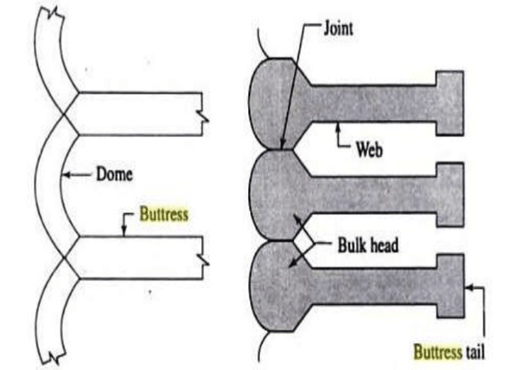
The massive head together with the buttress provides stability to the dam. Further, it can be constructed as a monolith construction. Further, there is not deck as another type of buttress dams.
However, since there is the fairly high thickness of concrete is to be poured, attention shall be made on concrete pouring.
In addition, functional requirements such as outlets, spillways, etc shall be planed without making many changes to the structural system that provides the stability of the structure.
As per the nature of the structure, it is required to increase the dimensions of the head to maintain the dam stability.
Further, loads are concentrated especially at the massive head. Therefore, the condition of the ground shall be suitable to do this kind of construction.
Advantages of Buttress Dam
- Buttress dams are not that heavy as other dams as it has higher lever arm against overturning with the addition of the buttresses.
- It can be constructed with comparatively thinner elements.
- The economy can be achieved by very the thickness of the deck and buttress.
- The deflection of the dam body is comparatively less when compared with other dams such as arch dams.
- Significant reduction of the concrete volume ( 1/2 to 1/3) when compared with a similar scale gravity dam.
Disadvantages of Buttress Dam
- Construction could be difficult compared with a simple gravity dam.
- The use of thinner concrete in the deck could lead to durability issues with the deterioration of concrete.
- High attention shall be paid during the operation period for dam safety.
- Since the stresses on the foundation are concentrated than uniformly distributed, the condition of the foundation rock shall be good enough to bear very loads in tall dams.
- Since there are construction joints in the dam body, careful attention is required to treat the joint and provide waterstops where necessary.
Hydraulic Fill Dam
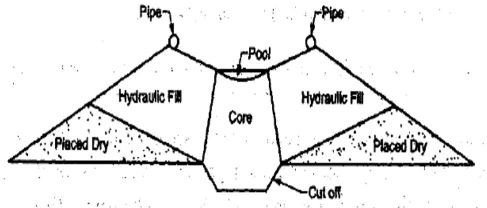
This an embankment type dam where it acts as a gravity structure.
Further, it is also can be recognized as a kind of an earth dam as per the materials available in the dam body.
The following key points can be highlighted in relation to these types of dam.
- Material transportation from the borrow pits and placement in the dam location is done by water.
- In such situations, the materials are mixed with water forming slush and they are transferred through the pipes to deposited near the dam face.
- In this process, the coarse materials stay near the face of the dame, and finer material moves toward the center and deposit there.
- The use of clay and silt in this method is not required compaction.
Refereces : Internet, wikipeda and relevant books.

