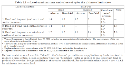
Different types of loads act on structures that shall be considered for the structural design based on their applicability. They can be classified as vertical loads and horizontal loads. Further, they can be separated as static and variable loads.
Loads that are not a function of the time can be considered as static loads and loads that varied with the time can be considered as variable loads.
Let’s discuss different types of loads one by one.
Dead Loads
All the structural elements are designed for dead loads and there are different types of loads such as super dead load, etc.. Further, dead loads are the permanent loads on the structure.
The self-weight of the structural element and the permanent loads on the structural are knowns as dead loads.
Weight of the structural elements, wall loads, permanent construction on a slab, etc is considered as dead loads.
BS 6399 Part 1 1996 could be referred for information about dead loads.
Live Loads
Variable loads applied to the structural elements are considered as live loads.
Minimum imposed loads on the applied on the floors based on the use of the structure can be obtained from BS 6399 Part 1 1996.
Wind Loads
In addition to the dead and live loads, the wind is the most widely considered type of loads applied load on structures is wind loads. With the increase of the height of the structure, wind pressure on the structure increase.
Wind action on smaller buildings is not considered usually because the notional loads become critical when wind pressure is smaller. However, when the building getting taller, wind pressure becomes critical.

There are different standards for the calculation of wind pressure on the structures. CP3 Chapter V and BS 6399 Part 2 1997 can use used to calculate the wind pressure on the structure. Further, now CP3 Chapter V has now been withdrawn. We may use the BS 6399 Part 2 1997.
Different standards are based on different average wind speeds. Therefore, it shall be careful when we selecting the basic wind speed.
CP 3 Chapter V uses the 3-second gust value and BS 6399 Part 2 uses the hourly mean wind speed. Therefore, when selecting wind speed, the appropriate value shall be selected based on the relevant code.
Earthquake Loads
Movement in the plates causes earthquakes. There are areas having a higher risk of earthquakes. When the distances from the plate boundaries are increasing, the impact of the earthquake is lesser.
The application of seismic loads on a structure is not common when compared with other types of loads.
Depending on the earthquake-prone area, the ground acceleration is considered for the design. In the design standards, acceleration coefficients for vertical acceleration and horizontal accelerations are provided for designers. These values are based on the probable magnitude of the earthquake.
The duration of an earthquake is about 30-40 seconds usually. There are occasions where the duration of much higher.
UBC is one of the most widely used structural design standards to calculate the earthquake effect on the structures.
Structural analysis and Design
There are different methods to calculate the lateral loads on the structures and carrying out structural analysis and design.
The easiest method is to calculate the earthquake forces as static loads and apply them to the structure to get the forces on the building. In this method, the base shear force is calculated based on the considered acceleration coefficients. Then this force is dived to the structure bases on the height and the mass of each floor. In this method, we assume the mass of the structure is lumped to find the responses.
In addition, the response spectrum method and time history method are available in most of the structural analysis software. After modifying the relevant functions, analysis can be done manually.
Blast Loads
Blast loads are not commonly applied types of loads on structures. Impact loads applied to a structure in a shorter period of time is the action of the blast loads. The Buring of blasting materials releases huge energy. This energy converted into thermal and kinematic energy.

Pressure waves are generated due to this reason. They travel in the air and hit on the structure causing damages to them.
The formation and blast pressure variation at a point is represented in the following figure.

As indicated in the above figure, there are positive and negative phases for blast pressure. Further, when the blasts occurred near the ground level, blast pressure increases significantly due to the ground reflections. This wave is called the reflected pressure which forms by margin g the incident wave and reflected wave.
Further, this merging forme the march stems that generates a uniform pressure at a given time in a point.
The magnitude of the blast pressure generated in a blast is a function of the scale distance. Scale distance depends on standoff distance(distance between the structure and blasting location) and the weight of the blasting materials.
Z = R / W1/3
Where, Z is the scaled distance (m/kg1/3 or ft/lb1/3)
R is the standoff distance (m or ft)
W is the weight of blast material (kg or lb)
Blast pressure variation is simplified during the design due to the difficulty in using the pressure variation shown in the above figure. The relevant parameters can be calculated form the UFC 3- 340-2 for positive and negative phases.
Facades are constructed in structures to protect the structures by cutoff the pressure waves entering into the building. Failure of the internal vertical load-carrying element could lead to failure of the structures. Further, the progressive collapse could occur in the structure based on the causes of the damage to the critical elements.
Thermal Loads
Variation of the temperature of the outside atmosphere affects the structures. It increases the temperature structures and that causes an increase in the internal stresses of structural elements.
The environmental temperature changes do not significantly affect the concrete structure leading to structural failures. However, it affects the durability of the structures. Articles durability requirements in reinforced concrete design and factors affecting durability of concrete discuss in detail on this subject.
Movement joints are constructed when the length of the structure is too long to reduce internal stresses. Rise of the internal stresses could cause structural cracks.
Thermal loads can make a considerable impact on steel structures. Steel is sensitive to the rise of the temperature. However, the steel structural element could not fail due to the changes in the environmental temperature. Bolt or the connection could be design considering these factors.
Settlement Loads
Structural settlement causes additional loads on structures to be encountered during the structural design. Variation of the condition of the ground could cause different settlements leading additional stress in the structural elements.
For example, consider the construction of the raft foundation on a ground where the part of the foundation is rested on the rock and another part is rested on the soil. If there is no movement joint at the change of the ground conditions, causing different settlement is inevitable.

The part of the foundation constructed on the soil could settle and the part of the foundation constructed on the rock does not move downward. This information shall be considered in the structural design with much care in consultation with the geotechnical engineer. When the foundation is designed, the subgrade reaction could be considered in the structural modeling to represent the different stiffness of the ground. Relevant stiffness shall be used in the structural model to represent the actual condition at the site.
It is common practice to model the foundation and superstructure separately in the structural analysis. However, when designing a structure of this nature ground, superstructure together with the foundation shall be modeled to get the actual impact on the other structural element in addition to the foundations. Further, consideration of the soil-structure interaction is a good option as discussed.


