UBC 1997 seismic desing procedure is not a complicated process and it can be adapted to the design very easily though it is believed that those calculations are complicated.
Before studying the UBC 1997 seismic design process and UBC 1997 seismic design example, let’s discuss a few basics of seismic design.
What is Earthquake?
It is shaking and vibration at the surface of the earth due to the underground movement of a fault plane or due to volcanic activity.
This results in a sudden release of energy and as a result, seismic waves are created.
There are three basic types of seismic waves.
- Primary (P) waves
- Secondary (S) waves
- Surface waves
The location of the earthquake is found using the primary and secondary waves.
Desing Concept for Earthquake Loads
Mainly the following two concepts are adopted to the structural system.
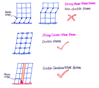
- Strong beam and weak column
- Ductile Cantilever wall system
Let’s move on to the main subject UBC 1997 Seismic Desing process.
Types of Seismic Analysis
Mainly there are two types of seismic analysis.
There are as follows.
- Static Analysis
- Dynamic Analysis.
Static Analysis
We applied the seismic loads to the structure as static loads and carrying the static load analysis.
The main factor is the consideration of earthquake forces as static.
In this method, we calculate the base shear as per the relevant parameters. Then the base shear is distributed over the structure according to its mass and height.
For example, consider a building having four floors. We considered the slump mass method to analyze the structure in this method. Mass of each floor is considered as a lump at floor level. Accordingly, the base shear is distributed over the building.
Though the loads are considered as static, material nonlinear can be considered in the analysis.
Dynamic Analysis
The dynamic action of the loads is considered in the analysis. Not only the material nonlinearity but also the load nonlinearity is also considered in the analysis.
There are two methods we used for dynamic analysis.
- Respond spectrum analysis
- Time history analysis
Load Combination UBC 1997
Ultimate limit state (ULS) load combinations shall be as follows.
- 1.4 D
- 1.2 D + 1.6 L + 0.5 [ Lr or S ]
- 1.2 D + 1.6 [ Lr or S ] + (f1L or 0.8 W)
- 1.2 D + 1.3 W + f1L + 0.5(Lr or S)
- 1.2 D + 1.0 E + (f1L + f2S)
- 0.9 D ± (1.0E or 1.3W)
Where, D – Dead Load, L – Live load, Lr – roof live load including any permanent reductions, S – Snow loads, W – wind load, E – Earthquake Load.
f1 = 1 for floors in place of public assembly, live loads exceeds 4.9 kN/m2, and for garage live load
Otherwise
f1 = 0.5
f2 = 0.7 for roof configurations (such as saw tooth) that do not shed snow off the structure
f2 = 0.2 for other roof configurations.
Note: Factored load combinations multiplied by 1.1 for concrete and masonry when load combination includes seismic forces.
Servisiblity Limit State (SLS) Load Combinations
- D
- D + L + (Lr or S)
- D + ( W or E / 1.4)
- 0.9 D ± e / 1.4
- D + 0.75[ L + (Lr or S) + (W or E /1.4)]
UBC 97 Seismic Design – Static Method
The following steps are followed when we design for static loads.
- Calculate the base shear using the relevant parameters.
- Then distribute the load according to the mass of each level and its height.
- Then we proceed with the analysis. In this analysis, we can consider the nonlinearity of other materials to get the most out of it.
- Further, the static method is more simple than any other method and easy to use.
Design Base Shear Calculation
The following equations are used to calculate the base shear force in the UBC 1997 seismic design process.
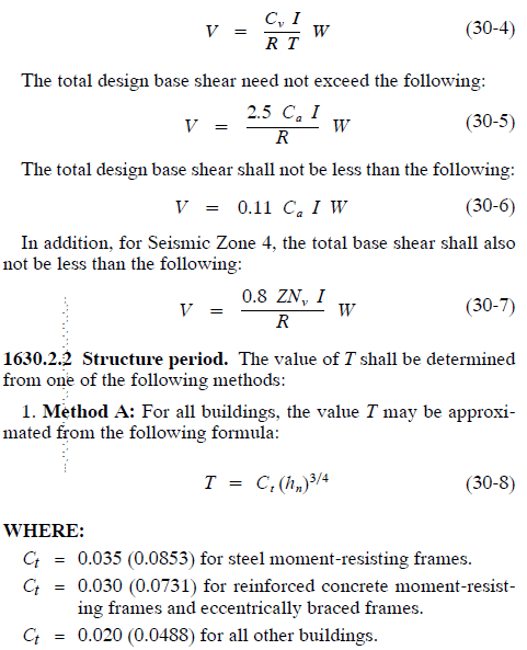
Depending on the period of the structure, we have to calculate the Ft that will be applied at the top of the structure.
The following text was extracted from the UBC 97 to elaborate on the method of the vertical distribution of forces.
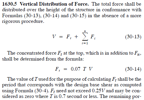
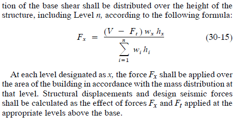
Using the equations 30-4 to 30-15, the static seismic force can be evaluated. The necessary parameters required in this calculation can be obtained from the table stipulated in the code.
- Z – Seismic zone factor: Table 16-I
- I – Seismci importance factor: Table 16-K
- R – Ductility coefficient: Table 16-N
- Ca – Seismic Coefficient: Table 16-Q
- Cv – Seismic Coefficient: Table 16-R
- Na – Near shear force Table 16-S
- Nv – Near source force Table 16-T
Let’s discuss some important factors in the UBC 1997 seismic design.
The article UBC 1997 Seismic Design Example could be referred to for more information on the design aspects and calculation methods.
Seismic Zone Factor – Z
This is the factor that represents the magnitude of the ground accelerations.
There are size zones as per the UBC 97. Each zone has a different peak ground acceleration. Further, there is a zonal map of the USA.
However, when we design our country, we may disregard the map and the appropriate zone shall be selected based on the peak ground acceleration that the structure to be design.
The following table indicates the UBC 97 zones and relevant peak ground accelerations.
| Zone | Z | Peak Ground Acceleration |
| 0 | 0 | 0 |
| 1 | 0.075 | 0.075g |
| 2A | 0.15 | 0.15g |
| 2B | 0.2 | 0.2g |
| 3 | 0.3 | 0.3g |
| 4 | 0.4 | 0.4g |
Further information on seismic zones, Wikipedia article, seismic zones could be referred to.
Storey Drift
Story drift needs to be limited to avoid any damages to the nonstructural elements. According to UBC 97, the following procedure shall be adopted.
ΔS = Design level response displacement.
This is obtained from the static analysis and it is the relative displacement at the level we consider.
ΔM = Maximum elastic response displaceemnt
This can be calculated from the following equation.
ΔM = 0.7RΔS
Limiting values of the story drift are classified based on the period of the structure.
ΔM ≤ 0.025h for T < 0.7 seconds
ΔM ≤ 0.02h for T ≥ 0.7 seconds
where h – storey height
The article different types of lateral loads could be referred to for more information on other types of applicable lateral loads. In addition, the article lateral load resisting systems could be referred to for more information.


